A
Sallen-Key 3-Pole Butterworth Active Highpass Filter - Design Sheet (DS2)
by John-Paul Bedinger
Of
the various topologies you can select for making active filters, the Sallen-Key
uses the least number of filter components. Furthermore, a 3-pole response (18 db/oct) is possible using only 1 op-amp. Below is a brief
mathematical description on how to compute the component values for a
Butterworth (steepest response with no ripple) 3-pole highpass filter with
selectable output gain.
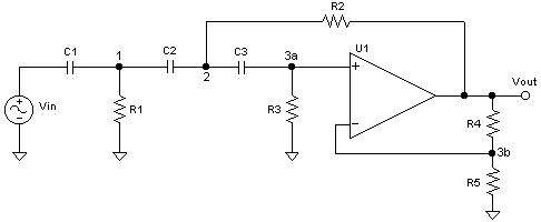
Diagram 1: A 3-pole
Sallen-Key highpass filter with output gain.
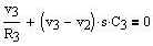
Looking at node 3b (where
v3 = v3a = v3b), the node voltage equation can be re-written to be:
 where
where
 and M defines the AC gain of the circuit in the passband (Eq. 1 and 2).
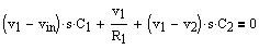
The rest of the node
voltage equations can be written:
 (Eq.
3)
(Eq.
3)
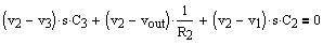 (Eq. 4)
 (Eq.
5)
(Eq.
5)
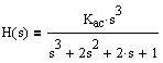
When solved for the filter
transfer function H(s) = Vout/Vin, we get:
 (Eq. 6)
Note that the standard
form of a 3-pole Butterworth highpass filter at cutoff frequency 1 rad/sec
is:
 (Eq.7)
where Kac is the AC gain of the filter, the same
as our M.
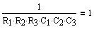
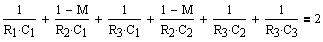
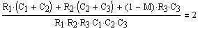
Equating like terms in
Equations 7 and 6 gives the solve block:
 (Eq.8)
 (Eq.9)
 (Eq.10)
 (Eq.11)
We choose our output
gain: Kac = M = 4 (12 dB)
Also, we choose values for
components: C1= 100 uF, C2=
100uF, C3= 100uF, R5= 10 k-ohms
Solving now for R1, R2, R3,and R4 gives (exact):
R1= 5 k-ohms, R2= 20
k-ohms, R3= 10 k-ohms, R4= 30 k-ohms
Rounding R1-R4 to standard
EIA 1% tolerance decade values gives:
R1= 4.99 k-ohms, R2= 20
k-ohms, R3= 10 k-ohms, R4= 30 k-ohms
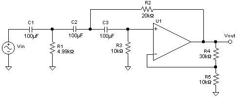
Diagram 2: A 3-pole
Sallen-Key Butterworth highpass filter with cutoff at 1 rad/sec and a gain of 4
(12dB).
Practical Notes:
·
For different
gain values you can refer to my table below, or resolve the solve block with a
different value of Kac. Use solutions only with all real positive roots. If you
have Mathcad(TM), you can download this
MathCAD worksheet to
help you.
·
C1, C2, and
C3 from the table can be scaled together by a factor y,
which should be done so that the source impedance Rin is much less than the
magnitude of the impedance (Rin + C1) at the cutoff frequency Fc.
This will set the cutoff frequency to 1/y rad/sec.
·
R1, R2, and R3
from the table can be scaled together by a factor x, which will
set the cutoff to 1/(x *y)
rad/sec, or:
|
M |
0dB |
6dB |
12dB |
18dB |
24dB |
30dB |
36dB |
|
R1(ohms) |
7180.57 |
5862.23 |
5000 |
4223 |
3531.2 |
2933.18 |
2425.61 |
|
R2(ohms) |
2819.43 |
11533.14 |
20000 |
31821.84 |
49433.83 |
76312.84 |
117808 |
|
R3(ohms) |
49394.66 |
14790.74 |
10000 |
7441.38 |
5728.67 |
4467.49 |
3499.48 |
|
R4(ohms) |
0 |
10000 |
30000 |
70000 |
15000 |
31000 |
63000 |
|
R5(ohms) |
infinite |
10000 |
10000 |
10000 |
1000 |
1000 |
1000 |
|
C1(Farads) |
100.E-6 |
100.E-6 |
100.E-6 |
100.E-6 |
100.E-6 |
100.E-6 |
100.E-6 |
|
C2(Farads) |
100.E-6 |
100.E-6 |
100.E-6 |
100.E-6 |
100.E-6 |
100.E-6 |
100.E-6 |
|
C3(Farads) |
100.E-6 |
100.E-6 |
100.E-6 |
100.E-6 |
100.E-6 |
100.E-6 |
100.E-6 |
|
M |
42dB |
48dB |
54dB |
60dB |
66dB |
72dB |
78dB |
|
R1(ohms) |
1998.55 |
1640.85 |
1342.31 |
1094.1 |
888.6151 |
719.3089 |
580.4752 |
|
R2(ohms) |
182295.4 |
282964.2 |
440633.6 |
688213.9 |
1077780 |
1691800 |
2660920 |
|
R3(ohms) |
2744.79 |
2153.77 |
1690.71 |
1328.07 |
1044.13 |
821.7427 |
647.4178 |
|
R4(ohms) |
127000 |
25500 |
51100 |
102300 |
20470 |
40950 |
81910 |
|
R5(ohms) |
1000 |
100 |
100 |
100 |
10 |
10 |
10 |
|
C1(Farads) |
100.E-6 |
100.E-6 |
100.E-6 |
100.E-6 |
100.E-6 |
100.E-6 |
100.E-6 |
|
C2(Farads) |
100.E-6 |
100.E-6 |
100.E-6 |
100.E-6 |
100.E-6 |
100.E-6 |
100.E-6 |
|
C3(Farads) |
100.E-6 |
100.E-6 |
100.E-6 |
100.E-6 |
100.E-6 |
100.E-6 |
100.E-6 |
Table 1: Prototype
component values for a Butterworth highpass filter response at 1 rad/sec.
Example:
We want Fc= 80 Hz,
C1= 0.1uF, C2= 0.1uF, and C3= 0.1uF, and a gain of 30 dB.
The source resistance is 220 ohms or less.
Use Table 1 for 30dB
prototype values, then scale y for the correct
capacitor range:
The scale factor y is
0.1uF/100uF, or y = 0.001. Thus, 80 Hz = 1/(2*3.1416*x*0.001).
Solving for x gives: x = 1.989
Scaling R1, R2, R3, and R4
by x gives:
R1= 5834.1 ohms, R2=
151786 ohms, R3= 8885.8 ohms, R4= 31 k-ohms, R5=1 k-ohm
Rounding R1-R4 to standard
EIA 1% tolerance decade values gives:
R1= 5.9 k-ohms, R2= 150
k-ohms, R3= 8.87 k-ohms, R4= 30.9 k-ohms, R5=1 k-ohm
The magnitude of (C1 +
Rin) at 80Hz is:
(1/(2*3.14*80*0.1e-6)^2+220^2)^.5 = 19.9 k-ohm at 80
Hz.
Since the combined
impedance of 19.9 k-ohm at the cutoff frequency is much greater than the 220 ohm source resistance by itself, the value for C1
should work well.
Change Log:
v.1.0.2 Removed some legal
rambling at the bottom of this change log – that’s all in the About This Site
and General Disclaimer now.
v.1.0.1 Made MathCad file
a zip file.
v.1.0 Initial release.