by John-Paul Bedinger
Of the various
topologies you can select for making active filters, the Sallen-Key uses the
least number of filter components. Furthermore, a 3-pole response (18 db/oct) is possible using only 1 op-amp. Below is a brief
mathematical description on how to compute the component values for a
Butterworth (steepest response with no ripple) 3-pole lowpass filter with
selectable output gain.
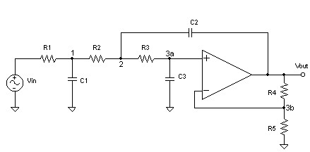
Diagram 1: A 3-pole Sallen-Key lowpass filter with
output gain.
Circuit Analysis:
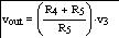
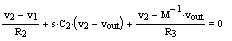
Looking at node 3b (where v3 = v3a = v3b) , the node voltage equation can be re-written to be:
 (Eq.
1)
(Eq.
1)
Let:
 Then:
Then:
 (Eq.
2)
(Eq.
2)
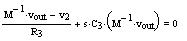
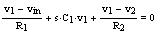
The rest of the node voltages can be written:
When solved for the filter transfer function H(s) = Vout/Vin, we get: H(s)=
 (Eq.
6)
(Eq.
6)
Note that the general form of a 3-pole Butterworth
lowpass filter at cutoff frequency 1 rad/sec is:
H(s) =
 (Eq.
7)
(Eq.
7)
Equating like terms in Equations 3 and 4 gives the
solve block:
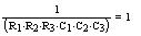
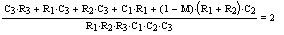
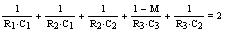
where Kac = M.
We choose our output gain: Kac =
3 (9.5 dB)
Also, we choose values for components: C1=
3000uF, C2= 1000uF, C3= 1000uF, R5= 10 k-ohms
Solving now for R1, R2, R3, and R4 gives:
R1= 816.46 ohms, R2= 481.26 ohms, R3= 848.33 ohms, R4=
10 kohms
Rounding R1-R4 to standard EIA 1% tolerance decade
values gives:
R1= 825 ohms, R2= 487 ohms, R3= 845 ohms, R4= 20
k-ohms
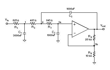
Diagram 2: A 3-pole Sallen-Key Butterworth lowpass
filter with cutoff at 1 rad/sec and a gain of 3.
Practical Notes:
·
For different
gain values you can refer to my table below, or resolve the solve block with a
different value of Kac. Use solutions only with all real positive roots. If you
have Mathcad(TM), you can download this MathCAD
worksheet to help you.
·
R1, R2, and R3
from the table can be scaled together by a factor x, which
should be done so that R1 is much greater than the source impedance at Vin.
This will set the cutoff to 1/x rad/sec.
· C1, C2, and C3 from the table can be scaled together by a factor y, which will set the cutoff frequency to 1/(x*y) rad/sec, or:
Fc = 1/(2*3.1416*x*y) Hz
|
M(Kac) |
0dB |
6dB |
12dB |
18dB |
24dB |
30dB |
36dB |
|
R1(ohms) |
1292 |
15652 |
1624 |
4305 |
3246 |
1437 |
3234 |
|
R2(ohms) |
2093 |
14694 |
4067 |
1750 |
2134 |
16260 |
7198 |
|
R3(ohms) |
3698 |
4348 |
15144 |
13276 |
1444 |
42794 |
42950 |
|
R4(ohms) |
0 |
10000 |
30000 |
70000 |
15000 |
31000 |
63000 |
|
R5(ohms) |
infinite |
10000 |
10000 |
10000 |
1000 |
1000 |
1000 |
|
C1(farads) |
1.E-3 |
100.E-6 |
1.E-3 |
1.E-3 |
1.E-3 |
1.E-3 |
1.E-3 |
|
C2(farads) |
1.E-3 |
100.E-6 |
100.E-6 |
100.E-6 |
100.E-6 |
10.E-6 |
10.E-6 |
|
C3(farads) |
100.E-6 |
100.E-6 |
100.E-6 |
100.E-6 |
1.E-3 |
100.E-6 |
100.E-6 |
|
M(Kac) |
42dB |
48dB |
54dB |
60dB |
66dB |
72dB |
78dB |
|
R1(ohms) |
1640 |
1242 |
2243 |
1030 |
1137 |
1700 |
6053 |
|
R2(ohms) |
13615 |
69066 |
32123 |
185004 |
285242 |
136533 |
47723 |
|
R3(ohms) |
4479 |
116556 |
138815 |
5249 |
308473 |
430832 |
346170 |
|
R4(ohms) |
127000 |
25500 |
51100 |
102300 |
20470 |
40950 |
81910 |
|
R5(ohms) |
1000 |
100 |
100 |
100 |
10 |
10 |
10 |
|
C1(farads) |
1.E-3 |
1.E-3 |
1.E-3 |
1.E-3 |
1.E-3 |
1.E-3 |
1.E-3 |
|
C2(farads) |
10.E-6 |
1.E-6 |
1.E-6 |
1.E-6 |
100.E-9 |
100.E-9 |
100.E-9 |
|
C3(farads) |
1.E-3 |
100.E-6 |
100.E-6 |
1.E-3 |
100.E-6 |
100.E-6 |
100.E-6 |
Table 1: Prototype component values for a Butterworth
filter response at 1 rad/sec.
Example:
We want Fc= 1000 Hz, C1= 0.1uF, C2= 0.1uF,
and C3= 0.1uF, and a gain of 6 dB. The source resistance is 10
ohms.
Use Table 1 for 6dB prototype values, then scale y for
the correct capacitor range:
The scale factor y is
0.1uF/100uF, or y = 0.001. Thus, 1000 Hz = 1/(2*3.1416*x*0.001).
Solving for x gives: x = 0.159
Scaling R1, R2, R3,and R4
by x gives:
R1= 2.489 kohms, R2= 2.336 kohms, R3= 691.3 ohms, R4=
10 kohms, R5=10 kohms
Rounding R1-R4 to standard EIA 5% tolerance decade
values gives:
R1= 2.4 kohms, R2= 2.4 kohms, R3= 680 ohms, R4= 10
kohms, R5=10 kohms
Since 2.4 kohms >> 10 ohms source resistance,
the value for R1 should work well.
Change Log:
v.1.3.2 Removed some legal rambling at the bottom of
this change log – that’s all in the About This Site and General Disclaimer now.
v.1.3.1 Made MathCad file a zip file.
v.1.3 Changed 66db gain resistors in Table 1. (Older
values were ok as well)
Moved
design sheet to new location on server.
Changed
title and included design sheet identifier (DS1)
v1.2 Made R5=10k in
solve block constants to match pictured results.
Corrected
component values for gains above 36dB in Table 1.
Made bigger
JPEG for diagram 1.
Added link
to Mathcad(TM) worksheet file.
Made
various small text formatting changes, and switched to Arial font.
Added this
change log.